
Så förändrar AI det dagliga arbetet i serviceteam
Minska nedtid och förbättra effektiviteten med AI‑baserad felsökning. Se hur ilean hjälper serviceteam att lösa problem snabbare och ta vara på kunskap.

Safety Factor Plots
I frequently get told that safety factor plots results within Nastran In-CAD are not correct. The reason for this is that safety factor values are calculated in a slightly different way.
This is best explained by the following example. I will use 200MPa for yield limit for comparison purposes
Safety factor calculation based on average stress at location A is 20.51
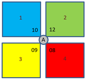 Average Stress value = (10+12+9+8)/4 = 9.75
Safety Factor = 200/9.75 = 20.51
Safety factor calculation based on how Nastran In-CAD displays plots at Location A is 20.97.
Safety Factor for Element 1 = 200/10 = 20
Safety Factor for Element 2 = 200/12 = 16.667
Safety Factor for Element 3 = 200/9 = 22.222
Safety Factor for Element 4 = 200/8 = 25
Average Safety Factor = (20+16.667+22.222+25)/4 = 20.97
So, this is the reason why there is slight difference in the safety factor results. Both results are correct as they have been calculated in slightly different ways. It is entirely up to you which value you take.
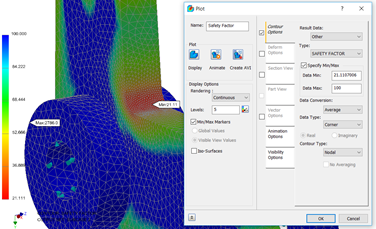 Here a safety factor display is showing a minimum value of 21.11.
Note changing Data Type to Corner or Centroidal will yield the same safety factor result.
So, for the same model and results if we display the average centroidal results the maximum stress value becomes 9.4381MPa.
So, based on this value the factor of safety (hand calculation) is 21.19.
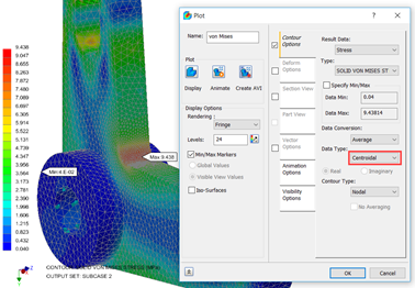 This is very close to the Safety Factor plot value of 21.11 with a difference of less than 0.5%.
There is also a great article on “Safety factor is not correctly reconciled in Autodesk Nastran In-CAD” by John Holtz from Autodesk which you may find very useful. (Available here)
NB: If you cannot wait and would like to learn more about Nastran In-CAD now then I would recommend the 'Up and Running with Autodesk Nastran In-CAD 2019' book available from Amazon worldwide.
If you would to watch some of the videos I have created around Autodesk Simulation then please take a look at our Simulation webinar library.
Minska nedtid och förbättra effektiviteten med AI‑baserad felsökning. Se hur ilean hjälper serviceteam att lösa problem snabbare och ta vara på kunskap.
Många företag har investerat stora summor pengar i BIM och digitala verktyg – men ändå uteblir den förväntade effekten. Varför? På BIM Summit by Symetri den 28:e april i år lyssnade jag till Erik Matton, psykolog, författare och grundare av Behaviour Design Group, och insåg att förändring inte bara drivs av teknik – vi får inte glömma att förändra våra beteenden.

Från produktionen på Skanska till en ledarroll inom infrateamet på Symetri. Martin Olsén berättar om sin karriärresa, drivkrafterna bakom arbetet och vad han anser är nyckeln till framgångsrika projekt.